We will be using LEGO NXT Mindstorm robots extensively in this class. If you want to learn about LEGO robots on your own, you should go to the LEGO Engineering web-site hosted by the Tufts CEEO. If you have worked with LEGO robots before you probably used the LEGO Mindstorm software of NXC. We will be using LabView by National Instruments. NI has some nice information on Lego Robots. Rob Torok from Down Under has some great tutorials on programming Lego robots with LabView. If you have time, I highly advise watching some of his tutorials. And you can even learn to speak Australian!
In class tomorrow you are going to use a LEGO robot. You are going to measure the velocity of this robot using one of the techniques you just studied. In order to make the robot move, you will need to write a simple computer program using LabView. We will be writing a program similar to what Rob Torok presents in his first video which I highly suggest you watch.
LabView is a visual programming language which uses icons. In the old days, when you wanted to perform a sophisticated experiment, you would have to build the eletronics for the experiment yourself. You would connect sets of transistors, resistors, capacitors and diodes with wires. This mess of electronics would be stuffed into a “black box.” On the front of the black box would be several dials, switches, and indicators along with input and output jacks.
Labview allows you to create your own experiments virtually. You create the inside of the Virtual Instrument (vi) in the “block diagram.” And the front of your instrument on the Front Panel. We are going to be using LabView for LEGO Mindstorms.
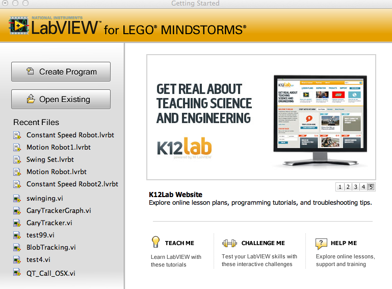
You will start by Creating a Program.
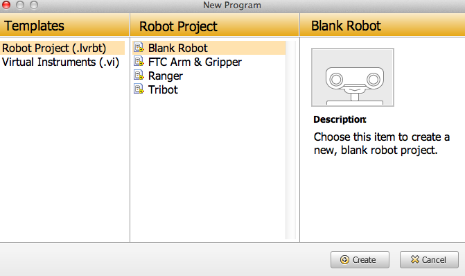
Next, you will create a robot project.
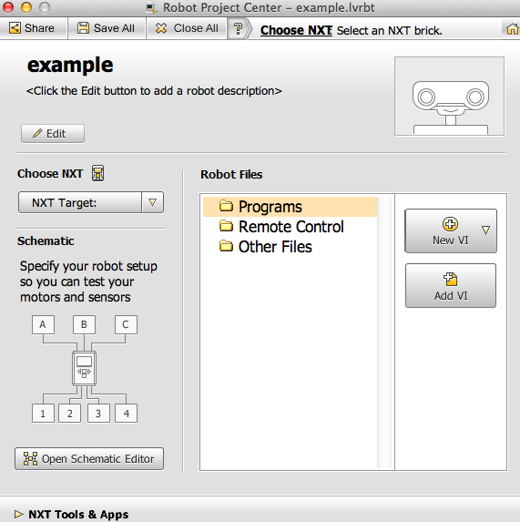
Then you will create a new VI, which stands for Virtual Instrument.
When you open the new VI, there are two parts. The Front Panel and the Block Diagram. 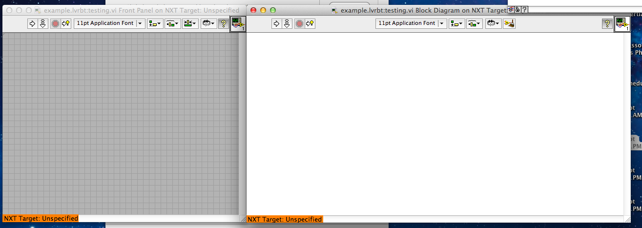
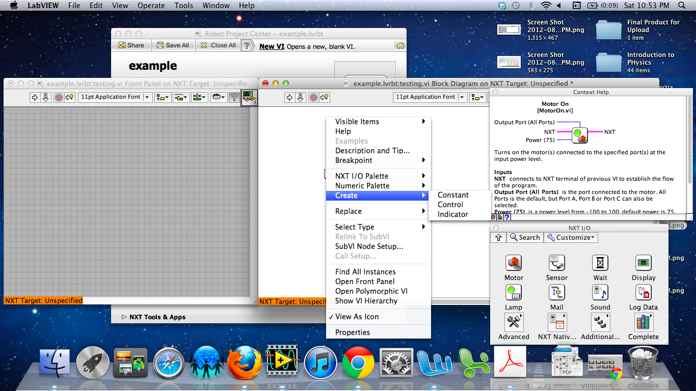
We will add elements of code to the Block Diagram. By right-clicking you will be able to add commands.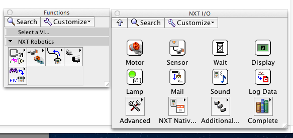
You may want to PIN the menu onto your screen so you can refer to it easily. You are going to select a motor. Drag a motor icon onto the Block Diagram.
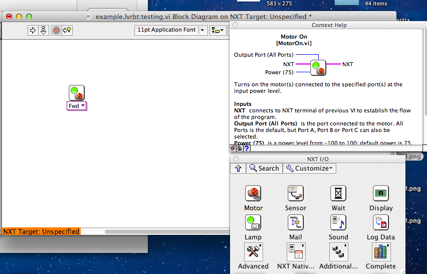
By selecting the help icon this gives you details and information about the icon you have selected. You can see there are lots of wires you can connect to the motor icon. The pink wires show how different parts of the code connect. The power lets the amount of power going into the motor. The blue port wire tells which motors get power.
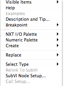 By right clicking on the motor icon where the Power wire would connect you get a menu. You want to create either a constant or a control. A constant will set the power level in your program. A control will allow you to adjust the power from the Front Panel.
After creating a control for the power, you could also set the Ports for your robot for wherever you have the motors connected.
Next, you need to tell your robot to continue moving using a wait command.
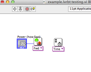 You need to connect the two commands with a Pink Wire. You also want your robot to move forward for several seconds so you can measure its speed.
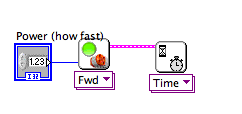
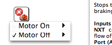
Lastly, you want your robot to stop after it has moved for several seconds. 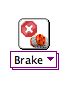 Drag another motor icon onto the Block Diagram . By clicking on the motor menu, you can change it from a Move Forward to a Brake icon.
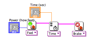
Your finished program should look similar to this: